Top Dock Leveler Installation Guide for Global Buyers
A dock is more than a steel bridge between a warehouse and a truck. It is a working interface where load weight, vehicle height, weather, traffic, and operator behavior meet. For global buyers, dock leveler installation must therefore begin with site evidence, not a catalogue picture. The World Bank’s Logistics Performance Index 2023 gathered feedback from 4,090 logistics professionals across 139 economies. Its findings underline a practical reality: reliable, predictable logistics depend on stronger physical infrastructure and better operational coordination.
This guide translates those concerns into installation decisions. It covers pit dimensions, dock height, hinge alignment, rated capacity, lip extension, drainage, bumpers, controls, and safe access. The MHI 2024 Annual Industry Report also identifies automation, workforce capability, and supply chain resilience as continuing investment priorities. A leveler should support those priorities without creating a new bottleneck. Measure twice. Weld once.
Experience shows that many failures begin before the equipment arrives. A truck profile may differ from the buyer’s specification. Concrete may appear sound but contain hidden cracks. Hydraulic lines may sit too close to forklift traffic. These details are easy to miss, even for experienced teams. The guide therefore combines manufacturer instructions, recognized safety practices, and on-site verification. EN 1398 and relevant local requirements can provide useful reference points, while OSHA rules may apply in the United States. Requirements differ across markets. Assumptions fail. Buyers should confirm structural loads, electrical conditions, inspection duties, and emergency procedures with qualified local professionals before commissioning the dock.
Define Dock Leveler Types, Capacity, and ANSI MH30.1 or EN 1398 Criteria
Top Dock Leveler Installation Guide for Global Buyers
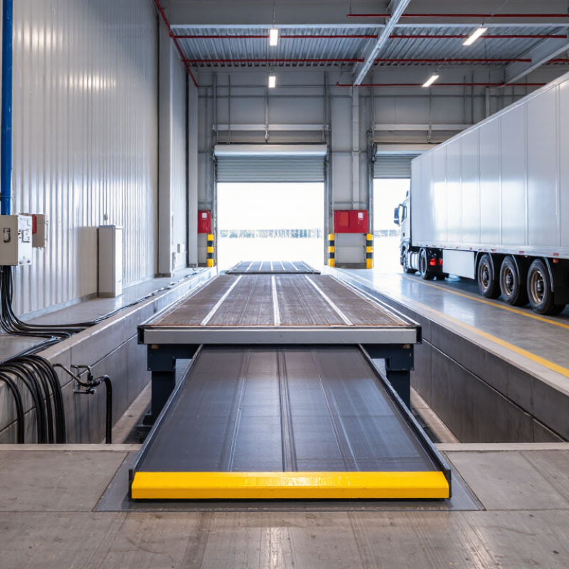
Dock levelers bridge the height gap between a warehouse floor and a trailer bed. Common types include mechanical, hydraulic, and air-powered models. Mechanical units suit moderate traffic and simpler maintenance. Hydraulic designs support frequent loading cycles with smoother lip control. Air-powered systems can reduce hydraulic leaks, but they need reliable air equipment.
Capacity must reflect the complete load, not only the forklift rating. Add the forklift, operator, pallet, and cargo weights. Then consider wheel loads, impact, approach speed, and uneven trailer movement. A 10,000-pound forklift does not automatically require a 10,000-pound leveler. That assumption is risky. Site measurements should record the dock height, pit length, trailer range, lip projection, and traffic frequency. ANSI MH30.1 provides performance and testing guidance for dock levelers in North America. EN 1398 defines safety and design requirements for European installations.
Standards are not interchangeable labels. Confirm the edition requested by the buyer, local building rules, and the manufacturer’s test documentation. EN 1398 also addresses rated load, structural safety, guarding, and operating controls. ANSI MH30.1 emphasizes capacity, deflection, fatigue, and safe operation. Industry accident data supports caution: the U.S. Bureau of Labor Statistics reported 1,069 workplace fatalities involving transportation and material-moving occupations in 2023. Not every incident involved a dock. Still, poor transitions can create serious exposure. A leveler may pass a basic capacity check yet fail during repeated impact. That is where installation judgment matters.
Top Dock Leveler Installation Guide for Global Buyers - Define Dock Leveler Types, Capacity, and ANSI MH30.1 or EN 1398 Criteria
| Dock Leveler Type |
Typical Capacity Range |
Typical Platform Size |
Operating Method |
Suitable Applications |
Key Installation Considerations |
| Mechanical Dock Leveler |
Approximately 9,000–35,000 lb (4,100–15,900 kg), depending on design |
Usually 6–7 ft wide × 6–8 ft long (1,830–2,135 mm × 1,830–2,440 mm) |
Spring-assisted mechanical lip and deck operation |
General warehouse loading where low complexity and manual operation are acceptable |
Requires accurate pit dimensions, adequate structural support, correct rear hinge alignment, and safe maintenance access |
| Hydraulic Dock Leveler |
Approximately 25,000–80,000 lb (11,300–36,300 kg), depending on rated load and vehicle traffic |
Commonly 6–7 ft wide × 6–8 ft long (1,830–2,135 mm × 1,830–2,440 mm) |
Hydraulic cylinders control the deck and hinged or telescopic lip |
High-throughput distribution centers, frequent forklift traffic, and heavy-duty loading |
Needs electrical power, protected hydraulic components, drainage planning, pit reinforcement, and commissioning by qualified personnel |
| Air-Powered Dock Leveler |
Typically approximately 20,000–35,000 lb (9,100–15,900 kg) |
Commonly 6–7 ft wide × 6–8 ft long (1,830–2,135 mm × 1,830–2,440 mm) |
An air bag or air-powered mechanism raises the deck; the lip extends onto the trailer |
Facilities seeking reduced hydraulic maintenance and moderate-to-high loading frequency |
Requires a suitable air supply, protection from puncture or abrasion, correct pit clearance, and safe controlled descent |
| Vertical-Storing Dock Leveler |
Commonly approximately 20,000–35,000 lb (9,100–15,900 kg) |
Often 6–7 ft wide × 6–8 ft long (1,830–2,135 mm × 1,830–2,440 mm) |
Platform stores in a raised vertical position inside the dock opening |
Temperature-controlled, hygienic, or security-sensitive facilities requiring a sealed dock interface |
Requires sufficient overhead and interior clearance, accurate vertical alignment, dock seals or shelters, and interlocked controls where specified |
| Telescopic-Lip Dock Leveler |
Often approximately 25,000–80,000 lb (11,300–36,300 kg) |
Commonly 6–7 ft wide × 6–8 ft long (1,830–2,135 mm × 1,830–2,440 mm) |
Extendable lip reaches the trailer deck while reducing the gap at the dock |
Mixed vehicle fleets, short trailer beds, and loading operations requiring precise lip placement |
Requires adequate lip extension, clearance for moving parts, accurate vehicle positioning, and inspection of the lip mechanism |
Capacity and Design Selection Matrix
| Selection Factor |
What to Calculate or Confirm |
Practical Guidance |
Installation or Procurement Check |
| Rated Capacity |
Total operating load, including the forklift, pallet, cargo, and any concentrated wheel loads |
Select a rated capacity above the maximum expected operating load; do not size only for the average shipment |
Request the manufacturer’s definition of capacity and confirm whether it is uniformly distributed, axle-based, or concentrated-wheel rated |
| Vehicle Height Range |
Highest and lowest trailer-bed elevations relative to the dock floor |
The leveler must bridge the complete vertical range without exceeding its permitted operating angle |
Measure the actual fleet, including air-suspension variation, small trucks, refrigerated trailers, and damaged or uneven docks |
| Lip Length and Engagement |
Required horizontal reach from the dock face to a safe bearing area on the vehicle deck |
The lip should rest securely on the trailer floor and maintain engagement during loading and unloading |
Confirm compatibility with trailer rear underride guards, dock bumpers, door geometry, and vehicle restraint procedures |
| Traffic Frequency |
Cycles per shift, shifts per day, and expected service life |
Frequent or multi-shift traffic generally favors powered equipment with durable wear components |
Include cycle testing, preventive maintenance intervals, replacement parts, and service access in the purchase specification |
| Pit and Structural Conditions |
Pit width, length, depth, front curb, rear hinge support, side clearances, and concrete condition |
A leveler should not be forced into a nonconforming pit; inaccurate dimensions can affect alignment, load transfer, and safe operation |
Use a site survey and approved installation drawings before cutting concrete or ordering a pit-mounted unit |
ANSI MH30.1 and EN 1398 Compliance Criteria
| Criteria Area |
ANSI MH30.1 Reference |
EN 1398 Reference |
Buyer Verification Evidence |
| Scope and Application |
Use the current applicable edition for powered and mechanical dock leveler design, performance, testing, and safety requirements |
European safety standard for dock levellers, including relevant mechanical, hydraulic, electrical, and operational safety provisions |
Obtain the declared standard, edition, model scope, and a compliance or test declaration applicable to the supplied configuration |
| Rated Load and Structural Performance |
Verify rated capacity, deck and lip strength, load application assumptions, and performance testing |
Verify rated load, stability, strength, deformation limits, and safe load transfer under the specified operating conditions |
Review load-rating plate, technical file, structural calculations or test records, and operating-load limitations |
| Vehicle Interface |
Confirm safe lip support, operating range, dock-to-trailer transition, and protection against unsafe movement |
Confirm safe engagement, usable operating range, edge protection, and prevention of hazardous gaps or uncontrolled movement |
Check lip engagement instructions, vehicle restraint integration, bumper position, and compatibility with the vehicle fleet |
| Controls and Emergency Functions |
Verify control layout, operating instructions, emergency stop or equivalent protective functions where applicable |
Verify control safety, prevention of unintended movement, emergency provisions, and clearly defined operating procedures |
Test controls, limit switches, warning devices, emergency functions, and restart behavior during commissioning |
| Guarding and Pinch-Point Protection |
Provide protection against accessible shear, crush, pinch, and entanglement hazards during normal operation and maintenance |
Address accessible hazardous zones, crushing and shearing points, and safe access for inspection and maintenance |
Inspect guards, side plates, toe guards, warning labels, maintenance supports, and safe working clearances |
| Documentation and Marking |
Provide capacity marking, instructions, maintenance information, and safety labels appropriate to the equipment |
Provide operating instructions, maintenance information, safety markings, and conformity documentation as applicable |
Require manuals in the user’s language, wiring and hydraulic diagrams, spare-parts information, inspection records, and serial identification |
Important: Capacity ranges and dimensions are typical planning values, not a substitute for the selected model’s technical data. The applicable standard, edition, national requirements, building code, electrical rules, and risk assessment should be confirmed before installation. Final pit dimensions, structural details, anchoring, testing, and commissioning must follow the approved installation drawings and qualified local procedures.
Survey the Pit and Confirm Dimensions, Clearances, and Structural Load Paths
Top Dock Leveler Installation Guide for Global Buyers
A reliable installation begins with a careful pit survey, not a rushed equipment order. Measure the pit length, width, depth, and sill height at several points. Concrete is rarely perfectly square. A laser level can reveal slopes that a tape measure misses. Record the dock face, door opening, truck bed range, and approach angle. Leave room for the leveler lip, hinges, bumpers, and maintenance access. Small errors can create large alignment problems.
Inspect the structure around the pit. Look for cracked concrete, hollow edges, exposed reinforcement, water damage, and previous repairs. Confirm that the supporting slab and walls can carry wheel loads, impact forces, and repeated cycles. The load path should be clear: platform to frame, frame to embedded steel or anchors, then into sound structural concrete. Do not assume a thin topping slab provides adequate support. A qualified structural professional should verify uncertain conditions and applicable local requirements.
Check nearby drains, lighting, fire systems, utilities, and door tracks before cutting or anchoring. Measure overhead and side clearances with the door fully open and the leveler raised. Photograph every measurement, mark reference points, and compare field data with the installation drawing. I have seen projects delayed by a single unrecorded drain. Recheck critical dimensions before fabrication. Even experienced teams miss details when the pit is dirty, crowded, or poorly lit. Accuracy improves when two people measure independently.
Install the Frame and Deck to Manufacturer Tolerances and OSHA 1910.26
Top Dock Leveler Installation Guide for Global Buyers
Install the frame on a clean, structurally sound dock face. Measure the opening before lifting any components. Small errors can create serious alignment problems later. Set the frame square, level, and within the manufacturer’s stated tolerances. Check both diagonals. They should match closely.
Secure the frame with approved anchors or welds specified in the installation drawings. Do not force a warped frame into position. Correct the supporting structure first. Install the deck only after the frame is stable. Confirm that hinges move freely and the deck rests evenly without binding. The lip should extend smoothly and meet the trailer floor safely. Follow the rated capacity and installation limits provided by the manufacturer.
OSHA 1910.26 requires dockboards to support intended loads and remain secured against movement. Verify that the installed leveler cannot slide, shift, or separate during loading. Keep access points clear, and inspect the deck, lip, hinges, and restraints before use. Local rules may add requirements.
Tips: Use a calibrated level, tape measure, and torque wrench. Record final measurements and anchor settings. Recheck the frame after the first loaded cycle. This step is often skipped. It should not be. A rushed installation may look acceptable, yet uneven gaps can reveal hidden stress. Have a qualified person review the work before operation.
Top Dock Leveler Installation Guide for Global Buyers
Install the frame and deck to the manufacturer's documented tolerances and verify safe dockboard conditions under OSHA 1910.26 requirements.
The chart presents practical field-control reference values commonly used during dock leveler installation. Actual frame, deck, pit, and lip tolerances must be taken from the approved manufacturer's installation drawings. OSHA requirements address safe use, load capacity, securing methods, and vehicle movement prevention; they do not establish one universal dimensional tolerance for every dock leveler.
Connect Hydraulic Systems and Verify the 20,000–80,000 lb Rated Capacity
A hydraulic dock leveler rated from 20,000 to 80,000 lb needs more than a matching pump. Confirm the platform rating, lip capacity, and concentrated wheel load separately. ANSI MH30.1 identifies dock-leveler safety, performance, and testing requirements. Use it as a verification reference, not as a substitute for site engineering.
Connect the hydraulic power unit with clean, correctly sized hoses. Keep suction lines short and protect them from sharp bends. Install the relief valve according to the hydraulic schematic.
Before energizing, inspect fittings, fill the reservoir with approved fluid, and bleed trapped air slowly. The platform should rise smoothly, without chatter, drift, or sudden lip movement. It should not “almost work.”
The U.S. Bureau of Labor Statistics recorded 1,069 fatal occupational injuries in transportation and material-moving occupations during 2023. That figure reinforces why commissioning must include controlled loading. Place the heaviest expected vehicle load on the deck, then check platform deflection, hinge movement, cylinder leakage, and structural contact points. Verify the actual capacity against the trailer floor height and forklift wheel loads. A dock marked 80,000 lb may still be unsuitable for a concentrated axle load. Record pressure readings, test weights, inspection dates, and corrective actions. Recheck after the first week of operation, because small hose leaks often appear only after repeated cycles.
Test Lip Extension, Vehicle Restraints, and Required Safety Interlocks
Top Dock Leveler Installation Guide for Global Buyers
A dock leveler is safe only when its lip, restraint, and interlocks work together. During commissioning, extend the lip fully onto the trailer floor. Measure contact length with the trailer parked at normal height. A short lip can slip during forklift entry. A long lip may strike the trailer wall. Test under realistic load conditions, not only during an empty-cycle check.
Vehicle restraints need a clear visual and physical confirmation. The restraint should engage the trailer’s rear impact guard before loading begins. OSHA reports about 34,900 serious forklift injuries annually in the United States. The BLS 2023 Census of Fatal Occupational Injuries recorded 1,942 fatal transportation incidents. These figures show why trailer movement deserves direct control. Required interlocks should prevent leveler deployment when the restraint is released. They should also stop loading if the dock door is not fully open. Verify warning lights, alarms, emergency stops, and manual overrides.
Tips:
Mark the lip’s safe contact zone with durable paint. Record extension, restraint engagement, and interlock results. Test cold starts and power failures. Small details matter. I have seen installations pass a checklist yet fail when a trailer stood slightly low. That gap needs review, not excuses. Reference ANSI MH30.1, EN 1398, OSHA forklift guidance, and local regulations before approval.